Spindle Angle

I can easily do that, but I'm wondering, what it is that you're thinking? The arc itself will never change, regardless of how much castor is put into the spindle! If I take the kingpin inclination out, and only use castor, that arc goes away.
It would not be an accurate representaion with out the kingpin angle .
When you turn right the spindle tip goes down relative to the ground and rises up when you turn left .
Maybe a 2d drawing won't show that .
 
This picture shows a 15° kingpin inclination spindle. If I turn the spindle right or left, 45°, you can see that the tip of the spindle is forced down .377". It's the same on both ends. You can see the arc of the redline. In fact, any jacking affect of kingpin inclination is canceled out as you turn from right to left. Many years ago it was used in automobiles to help vehicle tracking as it traveled down the road as the steering would move to the high point of the arc. I've built karts with no kingpin inclination that handled really well. It is my belief that karts have no need of kingpin inclination. My experience leads me to believe that.
View attachment 6835
The thing that needs looked at is the camber gain when the spindle end is forced down.
Is that good for handling? Both inside tire, and outside tire?

Now add caster to the mix and see what happens to camber.
 
The thing that needs looked at is the camber gain when the spindle end is forced down.
Is that good for handling? Both inside tire, and outside tire?

Now add caster to the mix and see what happens to camber.
KING PIN DEMO 3.jpg
12° Castor, 12° kingpin inclination, 0 camber.
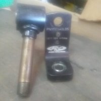
Can somebody send me, or post, a picture of a right side LTO spindle, without the tire?
 
I've been wondering, would it be feasible to sell spindles with camber angle already welded into them? It would eliminate changing kingpin angle when you change camber. I'm pretty sure buying a custom angle spindle would be cheaper than buying tires and wheels.
 
Bad pictures , id have to clean up an take it down for anything better .
On kart is right side , off kart is left 5-6 kpi .
20191105_131110.jpg20191105_130740.jpg
 
Last edited:
Couple of things to clarify.

When talking about KPI, we are actually considering the angle from perpendicular to the centerline of the spindle. This angle never changes when we adjust static camber.

Although it is easier to show the movement of the end of the spindle, the chassis never actually sees this movement. To see the actual effect, we must consider what the chassis sees, which is movement at the centerline of the contact patch. (not the centerline of the tread)

I think if you accurately depict how we use caster, camber, and KPI in a lto chassis, relative to the tire contact patch on both sides, you will better understand why we use KPI.
Also will have a better understanding of how the chassis works the tires.

The goal of a straight rail, sprint type chassis is completely different.

I feel like we have covered this same ground before.
Bad pictures , id have to clean up an take it down for anything better .
On kart is right side , off kart is left 5-6 kpi .
View attachment 6842View attachment 6843
You can tell the Triton runs a 15 degree RS spindle.
I thought stock the LS spindle was 7.5? Change it to 5 for high bite or asphalt?
 
Please don't stop drawing just because you are not seeing what you would like to show, Al.

There is some more "magic" relating KPI to weight jacking you may also want to explore.

Great drawings, anyway.
 
Here is a drawing Al posted a few years ago, when we were discussing this same thing. Other than incorrectly noting the center of the contact patch for the purpose of describing scrub radius, it is a good depiction of our setup on the right front.

I think if you check, you will find very little weight jacking on turn in, in the range we actually use, because of the KPI/caster shown.
The curve Al showed earlier for 12/12 setup will help explain why.
1573057453521.png
 
Last edited:
Here is a drawing Al posted a few years ago, when we were discussing this same thing. Other than incorrectly noting the center of the contact patch for the purpose of describing scrub radius, it is a good depiction of our setup on the right front.

I think if you check, you will find very little weight jacking on turn in, in the range we actually use, because of the KPI/caster shown.
The curve Al showed earlier for 12/12 setup will help explain why.

View attachment 6861
ITS SO SMALL....
 
Although I really do appreciate your efforts to show past posts, for some reason your picture will not expand and it's too small now for me to read it. Maybe you could post it full-size?
I'm including my very last drawing showing 12° castor with 0° KPI. The numbers speak for themselves.

KING PIN DEMO 4.jpg
 
Back
Top