Part 2 of repairing bearing bore(s):
I will just explain how I go about aligning things on pretty much any engine case I’ve ever reworked.
Most of the time, my aim is to base crank centerline on where the seal bores are. I know… one would assume that seal bores and bearing bores should all be concentric, but it’s not “always” true, unfortunately. Also, if a bearing bore has had a loose bearing spinning in it, then it’s likely the bore did not “wear” perfectly concentric to the original bearing bore. Using the seal bores as the reference centerline is the best method, since those are the two bores we do not want to move or touch.
OK… so assumption #1: Line up the finished bearing bores concentric with the centerline between the 2 seal bores. (in other words, all 4 bores should be perfectly concentric when done).
My next “goal” is to do my best to remove the absolute minimum amount of aluminum on any other surface I am going to machine.
Now we choose a place to start, and that’s going to be the center/sealing face of each case half. On the rare occasion that I will machine that face, it’s because someone has asked for a very precise width between bearings.
So for this case, we’ll make assumption #2: We are not going to machine any material off the sealing faces of each case half.
_ _ _ _ _ _ _ _ _
“Usually”, what I will do is remove any alignment pins from the case halves (IF they can be removed), and I will lightly lap each case half on a piece of 400 grit sandpaper on the surface plate. More than anything, this will give a confirmation that the face is flat, which will be the starting point of things.
On my lathe, I use faceplates to do everything. My approach is to have a 1” thick disc/circle of aluminum that is typically around 8” in diameter, and it’s attached to the faceplate on the lathe via 3 “stand-offs”. I just use 3 pieces of 1” aluminum bar-stock with a ⅜” hole in the center, and the faceplate has 3 counterbored holes for SHC screws (heads need to be well below flush). Once this is mounted on the lathe, it can be skimmed flat. I usually skim the OD and also drill and tap a ½-13 thread in the center (more on that later). Each of my faceplates has hole patterns for different engines: obviously I have one for the KT100, and others can sometimes be used for more than one engine make or model. My lathe has a D1-6 spindle nose, so in my case…. every faceplate is mounted on its own D1-6 steel faceplate… I never take them apart.
The next step is deciding how each case half will be held. I have a cabinet full of various “adapters” I’ve made over the last 40 years for holding all types of engine cases. You only need one for each side of your Rotax, so at worst, you’ll need to make a two small parts. Generally speaking, there will be some sort of “face” on each case half that I choose to mount to for holding each case half. One side almost always has a face and register for an ignition stator, so that will take care of how to mount one of the halves, and the PTO side can sometimes be a bit more challenging.
Ultimately, the goal is to be able to…. mount each case half with the center/sealing face against the faceplate (which runs dead true since it’s been machined), and the lightly skim whatever surface you want to use as the mounting point when the case half is flipped over to do machine work on the bearing bore. Any adapters to be made should be dead parallel, so once the case half is mounted with bearing bore facing out, the face of the case runs dead true.
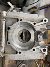
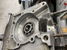
At this point (once all the above is done), the case should be indicated in so the seal bore runs dead true, and the bearing bore machined out to accept the sleeve. I try never to touch the back face during the process… I save that for when doing the finish machining on the bearing bore.
I should stress one final point, which really applies to any machining process being done on case halves or the complete case: ALWAYS use the least possible clamping force during every operation. If a case half is being held to the face plate with a few studs and nuts, tighten everything very lightly. Some cases can be very flexible, and simply do not have enough material to make them "robust". A KT100 case is a perfect example, but so is something like a vintage B-Bomb case. Everything being machined for ultimate accuracy should be held/clamped carefully and with very light clamping force.
The previous post should cover how to make the sleeves and drop them in once the case halves are machined, but fire away if you have questions. Next step will be how to do the finish work so everything is lined up perfectly.
Pics of a faceplate added. This happens to be one I made that will handle "most" older IAME cases. Bolt patterns for top, bottom and sides of cases.
PM